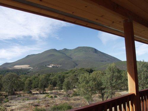
COBB – County officials will host a meeting this Tuesday, Oct. 27, on the proposed expansion of a geothermal project on Cobb Mountain.
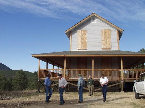
The meeting will take place from 5:30 p.m. to 7:30 p.m. at the Little Red Schoolhouse, 15780 Bottle Rock Road, Cobb.
County Community Development Department staff and and staff from the California Energy Commission will also be present at the scoping meeting, to answer questions concerning the petition to amend the Energy Commission Decision for the Bottle Rock Power Geothermal Power Plant.
The county is preparing an environmental impact report (EIR) for the proposed Bottle Rock Power Steam Project.
The project's owner, Bottle Rock Power GeoResource, has filed an application with the county for a conditional use permit, requiring the county to conduct an environmental review of the steam project, which would involve construction of two new well pads near the existing Bottle Rock Power generating facility, each with 11 production wells and one injection well, as well as associated access roads and pipelines.
County officials are cooperating with the California Energy Commission and the U.S. Bureau of Land Management (BLM) in the preparation of the EIR.
The Energy Commission has jurisdiction over the licensing of the Bottle Rock plant, but the production and injection wells and associated infrastructure, including pipelines and access roads, are exempt from the Energy Commission’s process and instead fall under the jurisdiction of the county.
BLM well permits are required because the new steam field is on private land with federal mineral rights. BRP GeoResource has already been issued a geothermal lease by BLM. Both the Energy Commission and BLM will issue separate noticing for this project to meet those agencies obligations under the Warren-Alquist Act and the National Environmental Policy Act (NEPA), respectively.
The county, the Energy Commission and BLM will coordinate their processes and documents to the extent feasible. The county has contracted with a consultant company, EDAW, to prepare the EIR, with direction from the county and input and review by the Energy Commission and BLM.
The following information details the site, location and scope of the project.
LOCATION
The project is located within a leasehold of approximately 350 acres known as the Francisco Leasehold on High Valley Road, Glenbrook Area, Lake County, California, within the Geysers Known Geothermal Resource Area (KGRA).
PROJECT DESCRIPTION – LEASEHOLD AREAS AND WELL FIELDS
The existing steam field providing resource to Bottle Rock Power (BRP) is located on the Francisco Leasehold, held by Bottle Rock Power, and consists of nine active production wells, two active injection wells and four suspended production/injection wells. The proposed well pads would be located on the BRP GeoResource Leasehold located just north of the Francisco Leasehold. Two well pads would be constructed on the BRP GeoResource Leasehold (well pads 1-31 and 2-31). Well pad 1-31 (West pad) would be located approximately 0.5 miles west of High Valley Road. Well pad 2-31 (East pad) would be located immediately west of and adjacent to High Valley Road.
DESCRIPTION OF SITE CONDITIONS
The general locations for the two well pads were originally identified during the mid1980s when the Department of Water Resources (DWR) held the geothermal rights (then known as the Binkley Leasehold) and planned to develop the geothermal resources. The well pads were never constructed although the East pad was permitted. DWR maintained ownership until the mid 1990’s until a decision was made to relinquish the rights to the geothermal resource. At that time mineral ownership reverted to the Bureau of Land Management (BLM).
BRP completed an analysis of potential sites for well pads throughout the leasehold, when it became apparent that the BLM intended to offer the lease for competitive bidding under the newly promulgated 2005 Energy Policy Act regulations. The analysis concluded that the two original locations still represented the most appropriate locations for drilling. The primary criteria for selecting well pad locations in The Geysers have been:
Absence of any landslide potential – any small mass movement could impact the integrity of shallow well casings;
Minimizing total area of disturbance;
Anticipation of major environmental constraints prior to detailed environmental analysis;
Ability to access all major geothermal resource targets within the lease using currently available directional drilling technologies.
The well pads do not appear to be located in areas with the potential for landslides, although all geotechnical evaluations for the West pad are not yet complete. Surface disturbance for both well pads was minimized by the placement of the pads in topographic areas that would require grading without extensive use of spoils areas.
Analysis completed by BRP GeoResource indicated only one previously known, specific, environmental constraint. The original location for the DWR West pad was close to an identified archaeological site, CA-LAK-1180. The West pad for the BRP Steam Project was re-positioned to the west-southwest of the original DWR location in order to avoid impacts to this archaeological site.
The two selected well pads will allow drilling access to most of the lease with ease. Directional drilling techniques allow well targets to be tested, not only at the correct location and depth, but also from wells drilled in the most appropriate direction with respect to regional stress fields.
WELL PADS
The sites for the proposed well pads were originally determined during the mid-1980s when DWR held the geothermal rights and planned to develop the geothermal resource. The well pads were never constructed but later analysis by BRP confirmed these sites were still the most appropriate for drilling. The well pad locations appear to be located away from areas with landslide potential and surface disturbance would be minimized by their placement in topographic areas that would require grading without extensive use of spoils. Well pad placement was also determined by the anticipation of other environmental constraints (e.g., noise, geology, and water resources) and ability to access all major geothermal resource targets within the leasehold using directional drilling technologies.
The operational area of each well pad would be approximately 3.2 acres in size but construction of the pads would disturb an area of approximately 8.3 acres for the West pad and 8 acres for the East pad. Access to the East pad would disturb approximately 5.2 acres. Actual dimensions of each well pad would be modified to best match the specific physical and environmental characteristics of the project area to minimize cut and fill and ground disturbance. A geotechnical study would be completed prior to construction for slope stability analysis to minimize the chances of landslides and other geologic hazards.
Well pad preparation activities would include clearing, earthwork, drainage, and other improvements necessary for efficient and safe operation as well as for fire prevention. The Lake County Grading Ordinance provides restrictions on grading activities between October 15 and April 15; grading during these restricted months requires a mitigation plan approved by Lake County prior to grading activities. All vegetation would be removed from the area of construction. Clearing would include removal of organic material, stumps, brush, and slash. One of the goals of site selection has been to balance the amount of cut and fill required for each well pad. Current estimates of cut and fill for the West pad is 55,000 cubic yards of cut and 95,000 cubic yards of fill. For the East pad a balanced cut and fill of 175,000 cubic yards is proposed. An additional 40,000 cubic yards of cut is proposed for the access road between the two pads.
Topsoil and other cut materials created during the construction of the well pads and access road would be used for fill purposes elsewhere on the two well pad sites. The marketable timber would be cut and stacked. The brush and stumps would be removed, stockpiled and burned or buried in spoil areas. Topsoil would be stockpiled for use in final soiling of fill areas. The stockpile areas would be in areas that are disturbed during the cut and fill process. Brush would be mulched and used in revegetation.
Both well pad sites would be prepared to create a level pad for the drill rig and a graded surface for the support equipment. The fill area would be keyed into undisturbed ground. The fill would be placed in 6 to 8 inch lifts and compacted using generally approved compaction equipment to 90 percent of the American Society for Testing and Materials (ASTM) D 1557 - 70 and the top two feet compacted to 95 percent. Cut slopes higher than thirty feet would be benched unless authorized by a registered civil engineer. The cut slope would be cut with a slope bar. A drainage system would be provided to carry away the water collected on the upper slopes and natural drainage systems. The drainage system would consist of ditches on the upslope perimeter of the well pads. These ditches would be sloped to drain at a gradient of 2 percent. Energy dissipaters would be installed where required. All machinery, drilling platforms, and oil and fuel storage would be in contained areas to prevent direct runoff. Fluids from these areas would be fully contained.
Well pad cut and fill slopes exposed by grading would be re-vegetated with approved grasses and/or woody plants and trees. The revegetation would be done the first fall after completion of construction prior to the start of the growing seasons in late summer or early fall in order to utilize the first light rains to germinate grass seeds. All seeds and propagules (such as tubers, offsets, or runners) used in revegetation of disturbed lands would be native species. A Seed Mix and Specifications Plan is proposed.
Well pad facilities would include the drill rig, water storage truck or tank, mud and water mixing tanks, an above ground diesel fuel storage tank, pipe rack, and drillers/geologist trailers.
WELL DRILLING
The wells would be drilled with a rotary drilling rig similar to those used throughout The Geysers. The drill rig would extend as much as 178 feet above the ground surface (depending on the type of rig used). Rig masts are made of a metal lattice and are painted red and white at the top and include flashing lights to meet Federal Aviation Administration (FAA) requirements.
Directional drilling may be conducted based on the location and extent of geothermal resources in proximity to the well site. Geothermal drilling permit applications would be submitted to the BLM for the drilling of these wells. A Drilling Plan would be prepared prior to drilling each well. The Drilling Plan would detail the drilling sequence of operations, the rig well pad layout, a well completion schematic, and a description and specification of the temporary noise barriers that are used for drilling.
The drilling program involves drilling a borehole to the reservoir formation at a measured depth of about 10,000 to 12,000 feet. The wells would be completed with a slotted liner through the production zone with a continuous string of production casing from the top of the production zone to the surface.
Wells would be drilled using a combination of bentonite-based mud and air drilling methods. The upper portion of the wells would be drilled using conventional mud drilling with surface casing set and cemented to approximately 3,000 feet and production casing set and cemented to between 6,000 to 7,000 feet, based on depth to the geothermal reservoir in the BRP GeoResource wells. Below the production casing, and through the steam reservoir, it is standard practice in The Geysers KGRA to drill with air in order to prevent damage to the reservoir by drilling muds migrating into the formation and reducing reservoir permeability.
A sumpless drilling process would be used to drill the borehole. A closed loop, mud circulating system, is being proposed for the project to eliminate the dumping of solids or liquids into the sump. The system would minimize the liquid and solid waste streams during the drilling operation by separation and drying of the solids and reclaiming water. During drilling operations a standard compartmentalized series of tanks, or mud pit system, would be used for solids processing as the drill cutting are brought to surface by the circulation of the drilling fluid. Using the surface tanks, mechanical solids removal equipment, chemical treatment and transfer pumps, the drilling fluid would be continuously circulated and processed in a closed loop system.
Drilling operations would be carried out 24 hours a day, seven days a week, until total depth is reached. An estimated 60 to 90 days would be required to drill and test each well, and approximately 12 to 15 field personnel would be working on each drilling operation at any one time. No camp sites or air strips would be required on the lease site. All support facilities for drilling operations would be located on the well pads. Drilling supervision would also be on site in trailers 24 hours a day.
STEAM AND INJECTION PIPELINES
The proposed steam pipeline would extend from the existing Francisco well pad (the closest location to interconnect to the existing steam pipeline to the power plant) and parallel High Valley Road to the west, and then parallel Saw Mill Road to the northwest. The steam pipeline would then bifurcate, with one segment paralleling a new access road to the west across High Valley Creek and up to the West pad, and the second segment extending north and then northeast to the East pad. A second steam pipeline eventually would be required to parallel the existing pipeline from the Francisco well pad to the main tie-in to the plant, and would be constructed parallel and adjacent to the existing steam pipeline from the Francisco pad to the tie-in for BRPP as steam volumes require. Pipelines, including insulation, are anticipated to be 30 inches in diameter, depending upon well productivity, and would be located above ground. Horizontal expansion loops (typically a square bend in the pipeline approximately 30 feet by 30 feet, would be constructed every 300 to 450 feet along the pipeline route to allow for thermal expansion. Depending on final steam pipeline alignment, some of the horizontal expansion loops may be eliminated as vertical road crossing loops may provide sufficient flexibility.
The project includes construction of an approximately 1.2-mile long, 4 to 6-inch diameter injection pipeline, to be located on stanchions with the steam pipeline, extending from the Francisco pad to the new well pads. An additional injection pipeline would be built on stanchions with the new steam pipeline from the main injection-tie in to the Francisco pad.
PROPOSED EQUIPMENT AND FACILITY IMPROVEMENTS
The project would contain the following features:
Addition of the West pad with up to 11 production wells and one injection well;
Addition of the East pad with up to 11 production wells and 1 injection well;
Construction of a new access road between well pads;
Addition of approximately 1.2 miles of insulated steam pipeline from the new well pads to the Francisco well pad header;
Addition of approximately 0.7 mile of new insulated steam pipeline from the Francisco pad parallel to the existing steam pipeline, to the tie-in point to the main steam pipeline line once sufficient steam is developed on the BRP GeoResource Leasehold;
Addition of an approximately 2-mile long, 4 to 6-inch diameter injection pipeline, to be located within the same corridor as the steam pipeline, extending from the main injection tie in at the plant to the new wells;
Addition of a remote telemetry and control building on each pad as well as distributed control systems at each site;
Backup standby power generation equipment to allow for well field control in the event of utility power failure;
Corrosion mitigation equipment and chemical storage facilities;
Minor power plant modifications to accommodate control and monitoring of the new steam field.
ACCESS ROADS
The West pad would be accessed via a new road to be constructed between the pads. The location of the access roads are shown in Figure 1.3.2. Access to both well pads for construction and post construction operation would be primarily along paved High Valley Road. High Valley Road will be maintained, as it already is, by Bottle Rock Power.
Access to the West pad would be along a new road that would run along the south side of the East pad and west to the West pad. The road would be approximately 20 feet wide and would require grading and removal of about 40,000 cubic yards of material in order to make the road safe and usable for transport of heavy equipment. Topsoil would be salvaged and stored at a designated staging area on the pads. Removed fill material would be properly disposed of or reused. This new road would have a maximum slope of about 15 percent. The access road would cross High Valley Creek at one location with a proposed culvert crossing. Installation of the culvert would include some excavation, if necessary, into the creek to clear vegetation and grading as necessary to install the new culvert. Bedding material would then be placed in the bottom of the excavation. The new culvert would be lowered in place over the bedding material with a backhoe that is staged along the existing roadway. The culvert would then be backfilled with soil and compacted as required by the project specifications. Alternately, culverts may be backfilled with concrete slurry. After culverts are backfilled, either sacked concrete or concrete headwalls would be installed at the inlet and outlet of the culvert. Concrete headwalls would be poured in place.
POTENTIAL ENVIRONMENTAL IMPACTS OF THE PROPOSED PROJECT
Based on the project description and the Lead Agency’s understanding of the environmental issues associated with the project, the following topics will be analyzed in detail in the EIR:
Aesthetics;
Air quality;
Biological resources;
Cultural resources;
Geology / soils and seismicity;
Hazards and hazardous materials;
Hydrology / water quality;
Land use/planning;
Noise;
Population/housing;
Public services/recreation;
Transportation / traffic;
Utilities / service systems.
For more information contact Lake County Community Development, 255 N. Forbes St., Lakeport, telephone 707-263-2221 or e-mail Community Development Director Rick Coel at This email address is being protected from spambots. You need JavaScript enabled to view it. .


